Ion Acceleration in Hybrid Magneto-Electrostatic Trap for Electrons: Cylindrical Hall Thruster
Scaling to low power Hall thrusters requires a discharge voltage or a discharge current to be decreased. The degree to which the first option can be accommodated is limited by the necessity to keep the exhaust ion velocity high. The second option implies that the propellant flow rate should be reduced. In order to maintain high propellant utilization efficiency at low propellant flow rates, the thruster channel must be scaled down to preserve the ionization probability. Thus, the acceleration region length, which is mainly determined by the magnetic field distribution, must be decreased linearly together with the channel sizes, while the magnetic field must be increased inversely to the scaling factor. However, the implementation of the latter requirement is technically challenging because of magnetic saturation in the miniaturized inner parts of the magnetic core. A linear scaling down of the magnetic circuit leaves almost no room for magnetic poles or for heat shields, making difficult the achievement of the optimal magnetic fields. Non-optimal magnetic fields result in enhanced power and ion losses, heating and erosion of the thruster parts, particularly the critical inner parts of the coaxial channel and magnetic circuit. Thus, miniaturizing the conventional geometry (annular) Hall thruster does not appear to be straightforward.

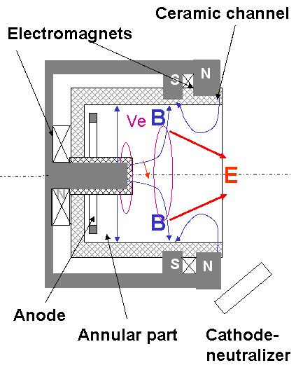
A cylindrical Hall thruster (CHT), is illustrated in the figure above. The thruster consists of a Boron-Nitride ceramic channel, an annular anode, which serves also as a gas distributor, two electromagnetic coils, and a magnetic core. What distinguishes this thruster from conventional annular and end-Hall thrusters is the cylindrical configuration with an enhanced radial component of the cusp-type magnetic field. The magnetic field lines intersect the ceramic channel walls. The electron drifts are closed, with the magnetic field lines forming equipotential surfaces, with E = - e v × B. Ion thrust is generated by the axial component of the Lorentz force, proportional to the radial magnetic field and the azimuthal electron current.
Compared to a conventional geometry (annular) Hall thruster, the CHT has lower surface-to-volume ratio and, therefore, potentially smaller wall losses in the channel. Having potentially smaller wall losses in the channel, a CHT should suffer lower erosion and heating of the thruster parts, particularly the critical inner parts of the channel and magnetic circuit. This makes the concept of a CHT very promising for low-power applications.
A relatively large 9 cm diameter (1 kW CHT) version of a cylindrical thruster exhibited performance comparable with conventional annular Hall thrusters in the sub-kilowatt power range. In recent work, a miniature 2.6 cm diameter CHT (100 W CHT) was studied and its performance was compared to that of the annular thruster of the same size. In the power range 50–300 W, the miniature cylindrical and annular thrusters were shown to have comparable efficiencies (15–32%) and thrusts (2.5–12 mN). It was found that both the 1 kW and 100 W CHT’s have unusually high propellant ionization efficiency, compared to conventional Hall thrusters. The ratio of the total ion current to the effective propellant mass flow current, in the case of the 100 W CHT, could exceed unity, which clearly indicates the presence of multi-charged Xe ions in the ion flux generated by the thruster.
Experiments with the 100 W cylindrical and annular Hall thrusters are conducted in the PPPL Small Hall Thruster Facility. Plasma diagnostics include various probes for measurements inside the thruster channel and in the plume.